Electrical circuit
An electrical circuit is a closed path or loop through which current flows. It mainly consists of a power source which can be AC or DC power. Examples of power sources are solar panels, generators, turbines and batteries. The closed path will be connected by conductors or wires from positive to negative in dc powered circuits or from live to neutral in ac powered circuits through a load. In this loop we can have switches, transformers, relays and various devices or instruments to control and regulate power in the circuit.
In this section will look at basic simple circuits which are a series circuit and a parallel circuit.
Before we get to that, let us look at some important laws. These are Kirchhoff’s Voltage law and Kirchhoff’s Current law, they are important when understanding and analysing circuits.
Kirchhoff’s Voltage law
Kirchhoff’s Voltage law states that the algebraic sum of potential rises and potential drops around a closed loop or path is zero. This can be simplified by understanding potential rises as positives and drops as negatives. If added together it should give us zero
Example : if we add (+5)+(-2)+(-3) = 0.
(+5) is the potential rise, (supply battery) and, (-2) and (-3) volt drop across resistors.
To further simplify the supply voltage is equal to the total volt drops added together in the series circuit. Kirchhoff’s Voltage law will apply mostly in series circuits.
Kirchhoff’s Current law
Kirchhoff’s Current law states that the algebraic sum of currents entering and leaving an area, system or junctions is zero. This can be simplified as the sum of currents entering an area, system or junction will be equal to the sum of currents leaving that area, system or junction.
Kirchhoff’s Current law is mostly applied to parallel circuits.
Series Circuit
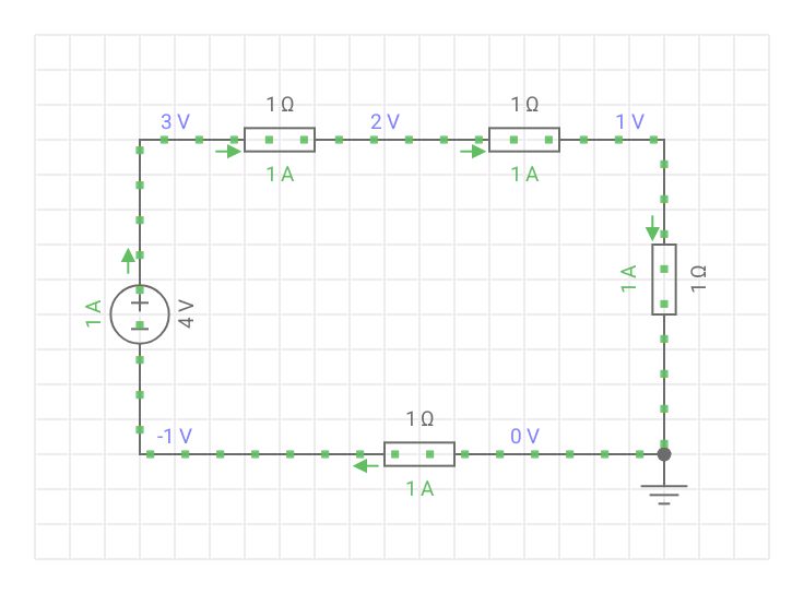
The series circuit can be described as a single loop. From Kirchhoff’s Voltage law, voltage drops across the loads(resistors in the diagram) will total the supply voltage. Current in a series circuit remains the same. As can be seen in the diagram above, current flows through the circuit without branching off. Therefore the current is equal throughout the circuit.
Just as voltage drops, we can simply add the resistor values up to get the total resistance of the whole series circuit.
R = R1+R2+R3+R4
V = V1+V2+V3+V4
I ( Current) remains constant
Parallel Circuit
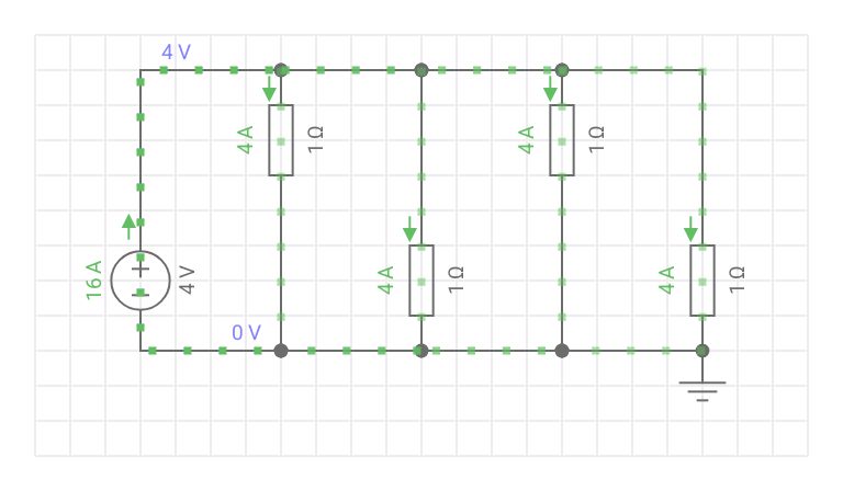
Voltage is the same across a parallel circuit. The voltage across all the resistors is the same as the supply voltage. Current branches off to each resistor. This means each branch as a different current. From Kirchhoff’s Current law the sum of all the currents from each branch will be equal to the supply current. The branch with the highest resistance will have the least current. The one with the lowest resistance will have the highest current. Remember Ohm’s Law current is inversely proportional to resistance. As resistance goes up the current goes down.
I =I1+I2+I3+I4
1/R =(1/R1)+(1/R2)+(1/R3)+(1/R4)
R =1÷(1/R1+ 1/R2+ 1/R3+ 1/R4)
Voltage is constant.
*Hint: The total resistance of parallel resistors is always less than the value of the smallest resistor.
When resistors are equal:
R(total)= R/N
Where N is the number of resistors in parallel.
Difference between series and parallel circuit
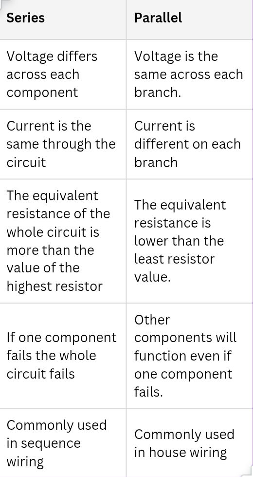
Series – Parallel Circuit
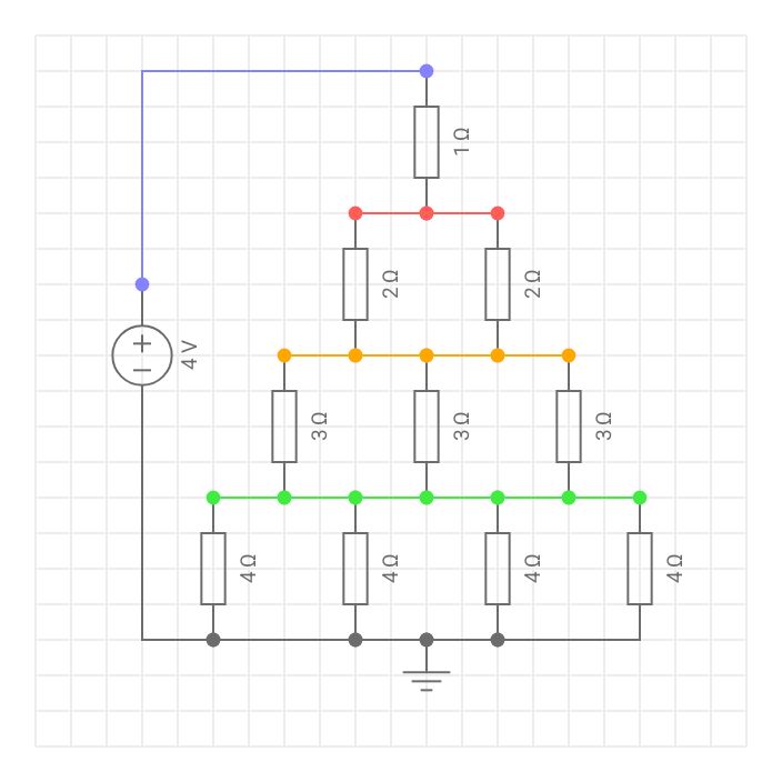
In reality most circuits will be a combination of both series and parallel circuits. The same rules still apply, the approach is to simplify the circuit. Work on the series part element and parallel work element separately until the circuit is simplified.
Test yourself
Try working out the voltages and currents in the following diagram.