On this page we will look at some common terms and principles which are popular when we talk about electricity.
We will start with voltage, current and resistance. But before we talk about their relationship, let’s define them and understand what they are.
Voltage
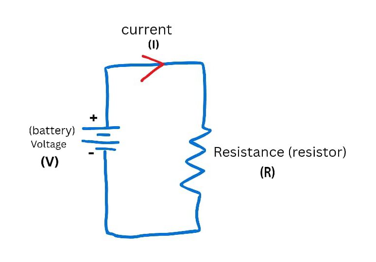
We can define voltage as the difference in electric potential (potential energy) between two points on a circuit. This difference results in electrical pressure that causes charged electrons to move in one common direction in a circuit.
This potential difference is what we term voltage. Voltage is measured in volts and is usually denoted by the letter V. The source of the potential difference can be a battery. Other common sources include solar panels, wind turbines, generators and electric sockets in our households via power stations.
Current
Curren can be defined as the flow of charged electrons in one common direction through conductive material in a circuit. The electrons flow from the negative terminal to the positive terminal, this is known as electron flow. This movement of electrons causes the movement of conventional current in the opposite direction, that is from positive to negative terminal.Therefore it can be said, without voltage we cannot have current.
Current is measured in amperes or simply amps. The symbol for amps is the capital letter A. That is the unit for current, example is 39 amps is written as 39A. The current itself is represented by the capital letter I in formulas and diagrams.
Resistance
Resistance can be defined as how much a material opposes the flow of electrical current. In other words how much it opposes the flow of charged electrons in a circuit. Resistance can be dependent on other factors such as the composition of the material( is it copper or silver), length, cross sectional area of the material and surrounding temperature. All these can have an effect on resistance.
Resistance is measured in Ohms. The symbol or unit for Ohms is Omega, represented by the omega sign Ω .
Resistors can be used to increase the resistance of a circuit. Resistors are usually used to get a desired outcome on the circuit. This is because of the relationship that exists between current, voltage and resistance. We will discuss this in the next topic.
Ohm’s Law
The relationship between voltage, current and resistance can be understood as defined by ohm’s law.
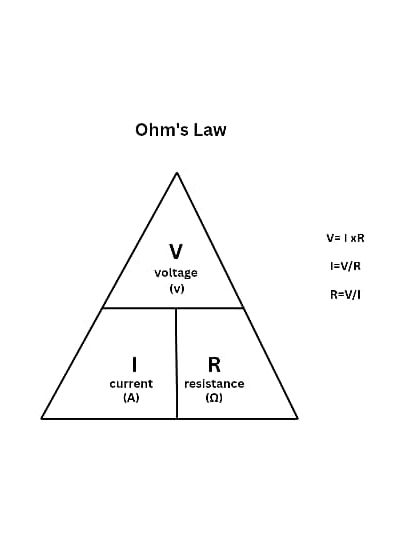
Ohm’s Law states that, the electric current flowing through a conductor is directly proportional to the voltage across it and inversely proportional to its resistance, as long as temperature and other physical conditions remain constant.
This can be seen by the formula:
V = I x R
Where V = Voltage, I = Current, R = Resistance.
From this formula we get
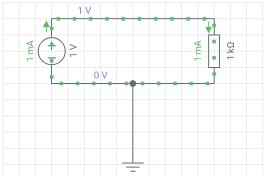
I = V/R , which is stated by ohm’s law
That is, Current is directly proportional to voltage and inversely proportional to resistance.
Simply put, Current increases as Voltage increases and Current decreases as Resistance increases.
AC vs DC Power Systems: What’s the Difference?
If you’re new to electrical work, or just trying to make sense of the systems you encounter every day, one of the first concepts to get comfortable with is the difference between AC (Alternating Current) and DC (Direct Current) power systems. Both are used to deliver electrical energy, but they behave very differently — and each has its place depending on the application.
What is DC (Direct Current)?
In a DC system, current flows in one direction only, at a constant voltage. Think of it as a steady, unchanging stream of electrical energy.
Common sources of DC power:
- Batteries (car batteries, phone batteries, solar batteries)
- Solar panels (before inversion)
- Fuel cells
- DC generators
Typical uses:
- Electronics (phones, laptops, circuit boards)
- Solar PV systems (DC is generated at the panel)
- Electric vehicles and battery storage systems
- Low-voltage control circuits in industrial equipment
What is AC (Alternating Current)?
In an AC system, the current periodically reverses direction, oscillating back and forth in a sine wave pattern. In most countries, this happens 50 or 60 times per second (50Hz or 60Hz).
Common sources of AC power:
- The national grid / utility power
- AC generators and alternators
- Power stations (coal, hydro, gas, nuclear)
Typical uses:
- Homes and buildings (lighting, appliances, HVAC)
- Industrial motors and machinery
- Long-distance power transmission
Key Differences at a Glance
FeatureDCACCurrent directionOne direction, constantReverses periodically (sine wave)VoltageConstantVaries (peaks and troughs)Transmission over long distancesLess efficient (historically)More efficient — easy to step up/down with transformersTypical sourcesBatteries, solar panels, DC generatorsGrid supply, alternators, power stationsCommon applicationsElectronics, EVs, solar storageHomes, industrial motors, power gridsSafety at high voltageCan be more dangerous to interrupt (no natural zero-crossing)Sine wave crosses zero, which historically made switching/interruption easier
Why Does the Grid Use AC?
The main reason global power grids run on AC rather than DC comes down to transformers. AC voltage can be stepped up to very high levels for efficient long-distance transmission (reducing energy loss), then stepped back down to safer levels for use in homes and factories — all using simple, reliable transformers. DC historically couldn’t do this as easily, which is part of why AC won the “War of Currents” against DC in the late 1800s.
That said, DC transmission has come a long way. High Voltage DC (HVDC) systems are now used for certain long-distance and undersea power links, because at very high voltages and long distances, DC can actually have lower transmission losses than AC. It’s a more specialized, capital-intensive technology, but it shows the two aren’t strictly “old vs new” — each has situations where it makes more engineering sense.
Where You’ll See Both Working Together
Many modern systems actually combine AC and DC:
- Solar PV systems: Panels generate DC, which is then converted to AC (via an inverter) to feed into the home or grid.
- Variable Speed Drives (VSDs): Convert incoming AC to DC, then back to a controlled AC output, to precisely control motor speed — something I work with regularly in industrial maintenance.
- Data centres and telecom sites: Often run on DC internally for reliability, but draw AC from the grid and convert it.
Final Thoughts
Neither AC nor DC is simply “better” — they’re suited to different jobs. AC remains the backbone of how power is generated and distributed at scale, while DC dominates in electronics, batteries, and increasingly in renewable energy and specialized transmission applications. Understanding how and why each is used is fundamental for anyone working in electrical maintenance, installation, or design.
If you found this useful, check out more breakdowns like this on my YouTube channel— and let me know in the comments if you’d like a deeper dive into HVDC systems or how inverters work.

